Sheet 20 Revised 03 Aug 2026
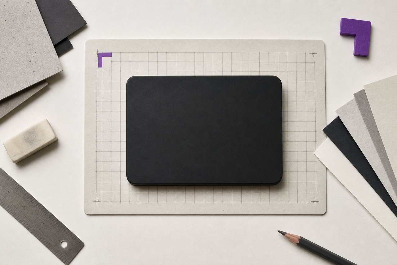
No. 132The subject is a rounded rectangle with a rounded rectangle inside it. Everything else is detail.
Vector phone tutorial: building a hard-surface object from primitives
A phone is the ideal first hard-surface subject: it is a rounded rectangle with a smaller rounded rectangle inside it and a few details, which means the whole drawing is primitives, offsets and subtractions. Every step below names the operation rather than a menu.
Set up before drawing
Work at a size where the smallest detail is comfortably visible: a body around a thousand units tall is convenient, because every subsequent measurement can be a round number and the whole drawing scales afterwards without loss.
Two habits from the start: name each shape as it is created, and put each stage on its own layer. Neither costs anything now and both decide whether the file is editable later.
Step 1: the body
Draw a rounded rectangle for the body. The proportion and the corner radius are the two decisions that make it read as this object rather than a card, so set the radius as a live, adjustable value rather than drawing it in permanently.
A useful relationship: the corner radius of the screen aperture is smaller than the body radius, but not proportionally smaller. The eye reads concentric corners as correct when the inner radius is roughly the outer radius minus the distance between the two edges, which is exactly what an offset produces.
Step 2: the screen, by offset rather than by scale
Duplicate the body and offset the path inward by the width of the bezel. Do not scale it down. Scaling produces a shape whose gap from the body varies between the long and short sides; offsetting produces a constant bezel, which is what the object actually has. This is the single most useful step in the tutorial and the one most often done wrong.
The offset also solves the corner radius automatically: an inward offset reduces the radius by exactly the offset distance, which is the relationship described above.
Step 3 (the apertures, by subtraction
Draw the camera aperture and the speaker slot as primitives) a circle and a rounded rectangle, and position them with the alignment tool set to a key object so they align to the body rather than to each other.
Then subtract them from the face. Use the non-destructive form of the operation. The result on screen is the same and the apertures remain individually adjustable, which they will need to be, because their position is the thing most likely to change.
Step 4: the side detail
Buttons and ports are small rounded rectangles positioned against the body edge. Two points decide whether this reads as a manufactured object.
Stroke weight consistency: every drawn edge in the object should use the same weight unless a difference is deliberate. Mixed weights read as a drawing rather than a product.
Spacing rhythm: buttons on the same edge should be separated by a repeating gap, and the gap should relate to the button height rather than being chosen freely.
Step 5: the highlight, by intersection
The single detail that makes a flat vector object read as a physical one is a highlight that follows the surface rather than sitting on top of it.
Draw a large soft shape crossing the face at an angle, then intersect it with a copy of the screen shape. The highlight is now clipped exactly to the surface it belongs to and it moves with it. A highlight drawn freehand and laid over the top will drift the moment anything is adjusted.
Keep it subtle. The most common failure at this step is a highlight strong enough to become the subject.
Step 6: check it small
Zoom out until the object is about forty pixels tall and look at it. If the apertures have vanished and the highlight has become a grey haze, the detail is finer than the size the drawing will be used at. This is the same test the marks on the logo side are put through, for the same reason.
What to keep in the file
The un-merged construction, the offset relationships intact, the shapes named, and one flattened export for delivery. The temptation at the end is to merge everything into a clean silhouette. Resist it in the working file and do it in the export, which is a copy.
Questions about the build
QueriesWhy offset the path instead of scaling the shape down?
Because scaling moves points away from a centre, so the gap between the outer and inner shape varies between the long and short sides. Offsetting keeps the distance constant everywhere, which is what a real bezel is, and it reduces the corner radius by exactly the right amount as a side effect.
How do I make a vector object look like a physical product?
Consistent stroke weights, a spacing rhythm on the repeated details, and one highlight that is clipped to the surface it belongs to rather than laid over the top. The clipping is what makes it read as light on a surface instead of a shape on a drawing.
Should the shapes be merged when the drawing is finished?
In the export, yes. In the working file, no. A merged drawing is finished and cannot be adjusted; the export is a copy and can be regenerated at any time from a file that is still editable.
How many points should a curve like this need?
Fewer than most drawings use, and the test is mechanical rather than a matter of taste: put a point only where the curve changes direction, and let the handles carry everything between. A phone body of this kind resolves in four corner points per rounded rectangle. Extra points do not show at final size, but every one of them is a place the curve can be nudged out of true later, which is what makes a redrawn edge look subtly wrong without an obvious cause.
Read next
TransfersVector basics
Primitives, booleans, paths, and the habits that keep a drawing editable a year after it is finished.
No. 214TutorialsIllustrator versus CorelDRAW
Four differences that survive scrutiny, and the reason none of them is about drawing.
No. 045Logo DesignLogo design principles
Five tests a mark has to pass, ordered so that the one which kills most candidates is applied first.